What Is a Solid-State Battery? Chemistry, Limits, and What Buyers Should Know
A procurement engineer planning a 400 kWh commercial storage project asked a fair question recently: should the project wait for solid-state batteries? The headline that triggered it promised twice the driving range from nothing more than a change of cell chemistry. The honest answer is no, and the reason becomes clear once you know what a solid-state battery actually is.
A solid-state battery is a cell whose electrolyte is a solid material instead of the liquid or gel used in conventional lithium-ion designs. That one swap removes a flammable liquid, makes a lithium-metal anode practical, and lifts cell energy density from roughly 90-260 Wh/kg to a 350-500 Wh/kg target range. What it does not do, as of 2026, is beat lithium iron phosphate on cost per usable kilowatt-hour or on cycle life, the two figures that decide most stationary storage purchases.
What a Solid-State Battery Actually Is
Strip a standard lithium-ion cell down and four parts remain: a cathode, an anode, a thin porous separator, and a liquid electrolyte soaking into all of them. Ions travel through that liquid on every charge and discharge. In a solid-state battery, a solid film of ceramic, glass, sulfide or polymer composite carries the ions, and in a genuinely solid design it also separates the electrodes, so the porous separator disappears.
The electrolyte is the whole story
Liquid electrolytes are organic carbonate solvents holding a dissolved lithium salt. They conduct ions extremely well, which is much of why lithium-ion won, but they are flammable and vaporise under abuse, so designers add vents, fuses and pack-level suppression. A solid electrolyte removes the fuel load and the leak path, and it lets cells be stacked under pressure rather than sealed inside a metal can.
The difficulty sits at the interfaces. Two solid surfaces never touch perfectly, so contact resistance between electrolyte and electrode particles is higher than in a liquid-wetted cell, and many designs need sustained stack pressure in the megapascal range to keep those contacts alive for thousands of cycles.
Why the anode changes too
Graphite stores lithium between its layers. Lithium metal would store roughly ten times more per gram, but in a liquid cell it plates as dendrites that pierce the separator and short the cell. A stiff solid electrolyte can block that growth in principle, and that is where the density gain really comes from. The catch is volume change: a lithium-metal anode breathes as it cycles, and repeated expansion can delaminate a rigid interface.
Solid-State and Liquid-Electrolyte Cells Side by Side
Comparison based on published 2026 data; solid-state figures come from pilot and laboratory cells rather than mass-production specifications.
Parameter
Liquid-electrolyte Li-ion (LFP and NMC)
Solid-state today
Electrolyte
Liquid or gel organic solvent
Ceramic, glass, sulfide or polymer film
Separator
Porous polymer membrane required
Not used in a true solid cell
Anode material
Graphite or graphite-silicon blend
Lithium metal becomes possible
Cell energy density
90-160 Wh/kg (LFP), 200-260 Wh/kg (NMC)
350-500 Wh/kg in pilot cells
Fire behaviour
Flammable vapour, venting and suppression needed
Much less flammable, no liquid fuel load
Cycle life
3,000-6,000 cycles for LFP
Hundreds to about 1,000 cycles in published tests
Cold and heat
Derates below 0°C, cooling needed above 35°C
Wider window in theory, interface losses when cold
Cost and supply
Mass production, falling cost per kWh
Pilot scale, several times the cost
Commercial status
Shipping in volume today
Small cells in niche products
Read the last four rows together and the pattern is plain. Solid-state wins on density and fire behaviour, and it still loses on the metrics a stationary project is bought on: cycles, cost and proven supply. Weight and volume matter in a vehicle, where every kilogram costs range. They matter far less for a cabinet bolted to a concrete pad.
The Three Solid Electrolyte Families
Sulfide electrolytes
Highest conductivity of the three, approaching 10^-2 S/cm at room temperature, close to that of a liquid, and soft enough to deform and keep contact under moderate pressure. Their weakness is chemistry: sulfides react with moisture, so production needs dry rooms and the finished cell must be sealed against humid air.
Oxide electrolytes
Stable in air and tolerant of higher voltages, which suits high-nickel cathodes. They are brittle, need sintering above 1,000°C, and conduct less well, typically 10^-4 to 10^-3 S/cm. Oxide cells in practice often become thin-film or hybrid designs in which a polymer or gel fraction keeps the interfaces wetted.
Polymer and composite electrolytes
Flexible, easy to laminate, and already used in semi-solid cells shipped in limited volumes. Conductivity is temperature-dependent: classic polymer cells prefer to run at 60-80°C, which rules out most residential and building applications without active heating. Ceramic filler or a small liquid fraction fixes room-temperature performance, at the price of calling the result semi-solid rather than solid.
Why Stationary Storage Still Runs on Lithium-Ion
A storage cabinet on a concrete pad does not care how heavy it is. That one fact removes most of the solid-state advantage for grid, commercial and residential projects, and leaves four criteria where mature lithium iron phosphate is hard to beat:
Cost per usable kilowatt-hour: LFP cells are mass produced at scale, while solid-state cells stay at pilot production with material and yield costs several times higher.
Cycle life: field-proven LFP packs deliver 3,000-6,000 cycles at 80% depth of discharge and back ten-year warranties, against a few hundred to roughly 1,000 cycles in published solid-state tests.
Supply and service: LFP cells, modules and battery management hardware come from many sources with established service networks, while solid-state supply is concentrated and unproven in the field.
Thermal engineering is solved: air-cooled and liquid-cooled pack designs already hold LFP cells inside a safe band for a decade or more.
That is why a commercial site adding half a megawatt-hour this year is more likely to order an outdoor liquid-cooled cabinet in the 215-233 kWh class than to wait for a chemistry that has not reached volume production.
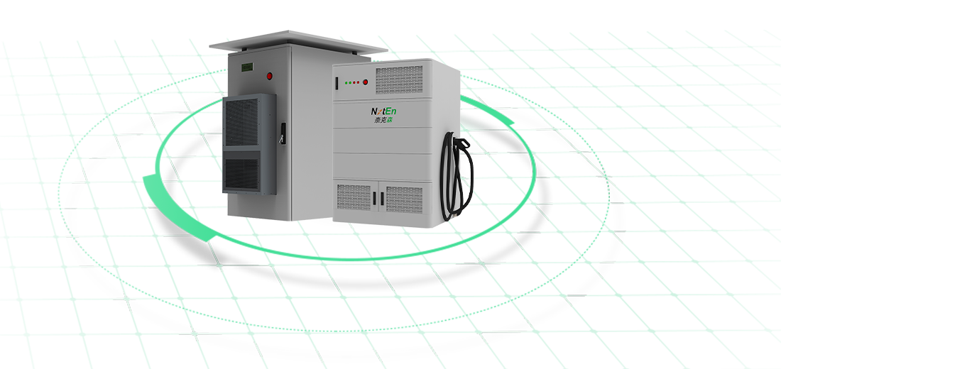
Outdoor Liquid-Cooled Commercial and Industrial Energy Storage CabinetA 215/233 kWh outdoor C&I cabinet with LFP, liquid cooling, PCS and EMS for projects seeking available storage rather than waiting for solid-state.View Product →
Where Solid-State Batteries Will Appear First
Commercialisation is running from small to large. Tiny solid-state cells already serve medical implants, wearables and some drone packs, where a high price per watt-hour is acceptable. Electric vehicles come next, because range sells cars: one recent industry report describes a solid-state design that aims to double the driving range of a comparable pack. Premium consumer electronics follow. Grid-scale and commercial storage sit at the back of the queue, as the application least sensitive to weight and most sensitive to cost per cycle.
Semi-solid and hybrid cells are the bridge. They keep a small liquid or gel fraction inside a composite electrolyte, ship in limited volumes today, and are sometimes marketed as solid-state even though the liquid phase has not been eliminated.
What to Verify Before You Buy, Solid-State or Not
Whatever chemistry ends up inside the cabinet, the questions that protect the purchase are the same:
Certification: UL 1973 and IEC 62619 are the baseline for stationary lithium systems, so ask for the certificate rather than a claim.
Warranty in writing: how many cycles, at what depth of discharge, and what capacity retention is guaranteed at the end of the term.
Cooling method: liquid cooling holds cell-to-cell temperature spread tighter than air cooling and slows calendar ageing in hot climates.
Traceability: a supplier that builds cells, modules and packs under one roof can trace a failure back to a batch, which a trading company cannot.
Delivery and spares: confirm lead time, spare module availability, and who performs warranty service in your region.
Treat any solid-state label on a shipping product as a claim to be tested rather than a specification to be trusted.
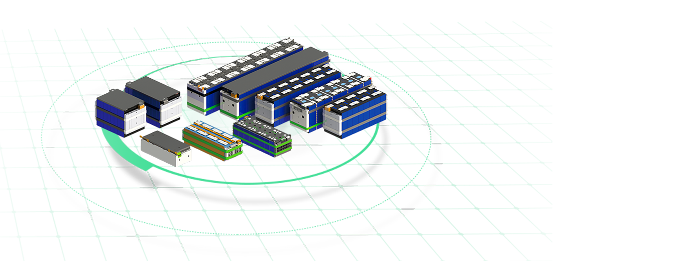
Liquid-Cooled Battery Energy Storage PackA liquid-cooled pack with sealed coolant circuit, IP67 protection and 7500-cycle cells for projects prioritizing reliability before solid-state production matures.View Product →
How a Vertically Integrated Supplier Fits In
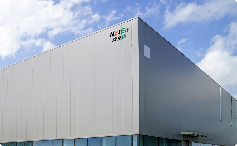
Until solid electrolytes reach volume production, project reliability depends on how well the cell, module, pack and system layers are engineered together. Nxten Energy builds across all four levels from its own factory in Yuyao, Zhejiang, and supplies components and finished systems rather than trading a single layer of the stack.
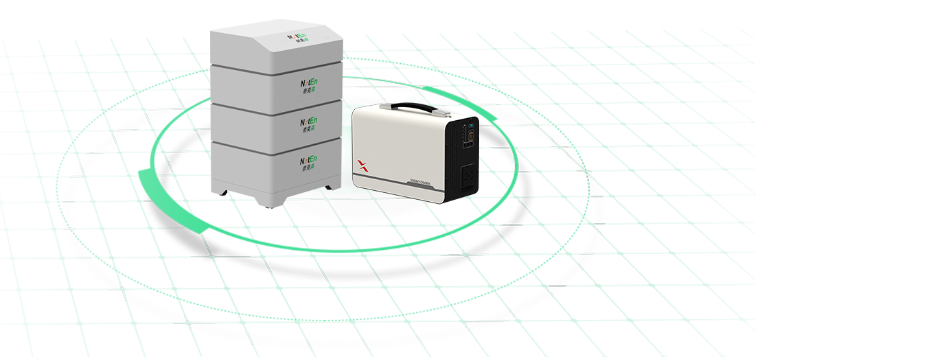
The current range covers portable packs, residential all-in-one systems, emergency batteries, off-grid hybrid systems that combine wind, solar, diesel and storage, outdoor industrial and commercial cabinets from 215 kWh to 400 kWh in air-cooled and liquid-cooled versions, and PV-storage-charging terminal systems. Manufacturing is certified to IATF 16949, the company states compliance with UL 1973 and IEC 62619, and the vertical structure leaves customers one point of responsibility for quality and delivery.
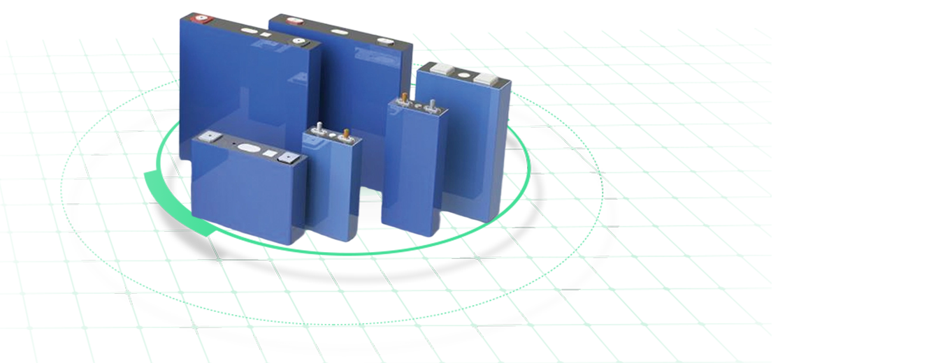
Lithium-Ion Battery Cells for Energy Storage and PowerLFP cell models from 50 Ah to 314 Ah support residential, commercial, grid and EV-charging storage, where liquid-electrolyte economics still matter.View Product →
A solid-state battery replaces the liquid electrolyte with a solid one, and the payoff is energy density and fire behaviour, not cost or cycle life. For an electric vehicle that trade is worth chasing. For a building, a factory or a microgrid, it does not change the arithmetic yet.
If a project needs storage this year, specify proven cells, insist on certified hardware, and match the cooling and warranty to the site. If it can wait, watch interface engineering and cycle-life data rather than announcements, because those are the numbers that will turn solid-state from a research topic into a purchasing decision.
.article-section{margin-bottom:40px;}
.article-section h2{font-size:22px;font-weight:bold;text-align:left;margin-bottom:12px!important;color:#028452;border-left:4px solid #028452;padding-left:12px;line-height:1.4;}
.article-section h3{font-size:16px;font-weight:bold;text-align:left;margin-bottom:12px;color:#0b6b46;}
.article-section p{font-size:16px!important;margin-bottom:12px;line-height:1.75;color:#333333;text-align:left;}
.article-section ul{margin-bottom:12px;list-style-type:disc;list-style-position:inside;padding-left:0;}
.article-section ol{margin-bottom:12px;list-style-type:decimal;list-style-position:inside;padding-left:0;}
.article-section li{list-style:inherit;font-size:16px;margin-bottom:6px;line-height:1.7;color:#333333;text-align:left;}
.article-section strong{color:#026b43;}
.article-section a{color:#028452;text-decoration:underline;}
.article-section table{display:table!important;text-align:center;border-collapse:collapse;width:100%;font-size:16px;margin-bottom:15px;}
.article-section thead{display:table-header-group!important;}
.article-section tbody{display:table-row-group!important;}
.article-section tr{display:table-row!important;}
.article-section th{display:table-cell!important;font-weight:bold;border:1px solid #cccccc;padding:8px;background:#eaf6f0;color:#026b43;font-size:16px;}
.article-section td{display:table-cell!important;border:1px solid #cccccc;padding:8px;font-size:16px;color:#333333;}
.article-section caption{caption-side:bottom;font-size:16px;margin-bottom:12px;font-style:italic;color:#808080;text-align:left;}
.article-section:nth-of-type(1){background:linear-gradient(135deg,#f2fbf6 0%,#e3f5eb 100%);border-left:4px solid #028452;border-radius:12px;padding:22px 24px;}
.article-section:nth-of-type(2) h3{border-bottom:1px dashed #cfe8dc;padding-bottom:6px;}
.article-section:nth-of-type(3){background:#f7faf8;border:1px solid #e2efe8;border-radius:12px;padding:22px 20px;}
.article-section:nth-of-type(4) h3{background:#eef7f2;border-left:3px solid #028452;border-radius:0 8px 8px 0;padding:8px 12px;}
.article-section:nth-of-type(5) ol li{background:#f6fbf8;border-left:3px solid #b8e0cc;border-radius:8px;padding:10px 12px;}
.article-section:nth-of-type(5) ol li::marker{color:#028452;font-weight:bold;}
.article-section:nth-of-type(6){background:#eef7f2;border:1px dashed #9ed4b8;border-radius:12px;padding:22px 24px;}
.article-section:nth-of-type(7) ul{background:#fbfdfc;border:1px solid #e3efe9;border-radius:10px;padding:16px 18px;}
.article-section:nth-of-type(7) ul li::marker{color:#028452;}
.article-section:nth-of-type(8){background:#ffffff;border:1px solid #d7ece1;border-radius:12px;padding:22px 24px;box-shadow:0 4px 14px rgba(2,132,82,0.08);}
.article-section:nth-of-type(9){background:#028452;border-radius:12px;padding:22px 24px;}
.article-section:nth-of-type(9) p{color:#ffffff;}
.product-card{display:block;margin:20px 0;border:1px solid #e5e7eb;border-radius:10px;overflow:hidden;font-style:normal;background:#fff;box-shadow:0 0 5px rgba(31,41,55,.08)}
.pc-inner{display:flex;text-decoration:none;color:inherit;align-items:center;min-height:148px}
.product-card .pc-img{width:auto!important;min-width:0!important;max-width:min(36%,240px)!important;height:auto!important;min-height:0!important;max-height:148px!important;aspect-ratio:auto!important;object-fit:contain!important;flex:0 0 auto;display:block;align-self:center}
.pc-body{padding:12px 16px;flex:1;min-width:0;display:flex;flex-direction:column;align-self:stretch;justify-content:center}
.pc-title{display:block;font-size:15px;font-weight:600;color:#111;margin:0 0 6px;line-height:1.4}
.pc-desc{display:-webkit-box;font-size:13px;color:#6b7280;margin:0 0 8px;line-height:1.5;overflow:hidden;-webkit-line-clamp:2;line-clamp:2;-webkit-box-orient:vertical}
.pc-cta{display:block;font-size:13px;font-weight:600;color:inherit;margin-top:auto}
.pc-inner:hover .pc-title{text-decoration:underline}
.article-section a:not(.pc-inner),article a:not(.pc-inner){color:inherit}.pc-cta{color:inherit!important}
![What Is a Solid-State Battery? Chemistry, Limits, and What Buyers Should Know]()



 +86-0574-62165160
 +86-18958222822
 No. 95-1, South Guangming Road, Simen Town, Yuyao City, Zhejiang Province, China



 English
 русский


 End-To-End Protection