

 English
 русский
Home / News / Industry News / Battery Energy Storage System Design: Core Components, Sizing & Optimization
Industry News

An industrial park in Zhejiang planned a 1 MW / 2 MWh behind-the-meter storage system to shave peak demand. The first design quoted by a battery pack supplier used 280 Ah cells in a simple rack arrangement with no liquid cooling between strings. Within three months, string imbalance triggered frequent BMS alarms and the system had to derate to 60% of rated power. The lesson is that battery energy storage system design is more than connecting cells; it is a process of balancing chemistry, thermal behavior, electronics, and safety from the first concept.
In this article, we break down the design process into the core components, sizing, thermal strategy, standards, and application-specific choices that determine whether a BESS becomes a profitable asset or an operational risk.
Every battery energy storage system, from a residential wall unit to a utility container, depends on the same six subsystems: battery cells, battery management system (BMS), power conversion system (PCS), thermal management, energy management system (EMS), and fire safety.
| Subsystem | Function | Design impact |
|---|---|---|
| Battery cells | Store electrochemical energy | Chemistry, capacity, cycle life |
| BMS | Monitor voltage, temperature, SOC | Balancing, overcurrent protection, alarms |
| PCS | Convert DC to AC and back | Efficiency, grid response speed |
| Thermal management | Remove or add heat | Service life, safety, power availability |
| EMS | Decide when to charge and discharge | Revenue or savings, grid code compliance |
| Fire safety | Detect and suppress thermal events | Risk mitigation, permitting approval |
The order in which you design these subsystems matters. Thermal management should be decided after the C-rate, not as an afterthought. A cell that performs well at 0.5 C may fail at 1 C without proper cooling.
Selecting a reliable cell is the foundation. A manufacturer that supplies cells with consistent capacity and low internal resistance makes the rest of the design easier.
Sizing starts with the grid objective, not the battery. For each application, the design must answer three questions: how much energy, how much power, and for how long.
For a typical behind-the-meter commercial system, a 2C design will have a much shorter cycle life than a 0.5C design. The table below shows common starting points.
| Application | Capacity | Power | Key constraint |
|---|---|---|---|
| Residential backup | 10–20 kWh | 5–10 kW | Quiet operation, small footprint |
| Commercial peak shaving | 200–500 kWh | 50–200 kW | Duration at rated power, response time |
| Off-grid hybrid | 100–1000 kWh | 30–500 kW | Deep cycles, generator integration |
Depth of discharge has a direct trade-off. Limiting DoD from 90% to 80% can increase cycle life by 20–30% for LFP cells, depending on the operating temperature. The sizing calculation must include that trade-off.
Heat is the enemy of lithium batteries. High temperatures accelerate capacity fade, while steep temperature gradients inside a rack cause cell-to-cell imbalance. Liquid cooling maintains the difference between the hottest and coolest cells within 2–3 °C, which forced-air cooling rarely achieves in high-density configurations.
| Cooling type | Temperature uniformity | System cost | Best for |
|---|---|---|---|
| Forced air | Moderate | Low | Small residential or portable packs |
| Liquid | High | Higher | Commercial and utility systems above 100 kWh |
If you are designing for a peak discharge longer than two hours, liquid cooling is often the safest choice. A good example is the liquid-cooled battery energy storage pack used in Nxten's outdoor cabinets. It keeps cell surfaces at a stable temperature even when ambient conditions exceed 40 °C.
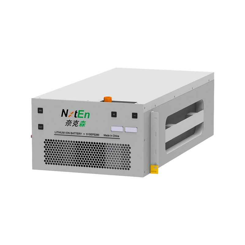
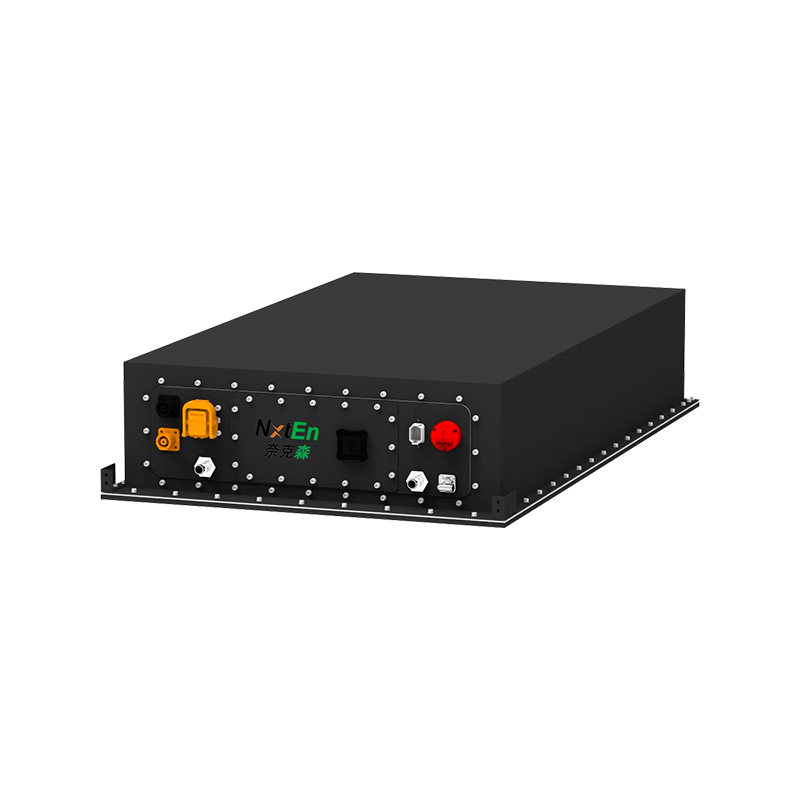 Liquid-Cooled Battery Energy Storage Pack for Long-Duration DischargeThis pack uses a sealed liquid cooling loop to keep cell temperatures uniform even above 40°C, making it suitable for peak discharges lasting over two hours. Its compact design and intelligent thermal management support reliable outdoor installation.View Product →
Certification standards are not administrative formalities. They force designers to consider failure modes that are easy to ignore in a spreadsheet. For most projects, you should require battery cells to meet IEC 62619 and complete packs to meet UL 1973. If the installation site is near vehicles or public areas, manufacturing under IATF 16949 adds traceability and process discipline.
In our own manufacturing process, we combine six-sigma quality control with vertical integration, so the same team responsible for cell consistency also handles pack assembly and final testing. This creates a single responsibility point for the customer.
The same architectural elements take different shapes in residential, commercial, and off-grid projects. The application controls the number of cycles per day, the acceptable noise level, and the maintenance budget.
Residential systems prioritize low acoustic, compact packaging, and seamless switchover. The design should include an emergency power supply with an external changeover and a clear way to monitor state of charge from a consumer app. Homeowners should also verify fault withstand capacity and thermal barriers inside the unit. For a deeper look, read our article on all-in-one residential energy storage system safety.
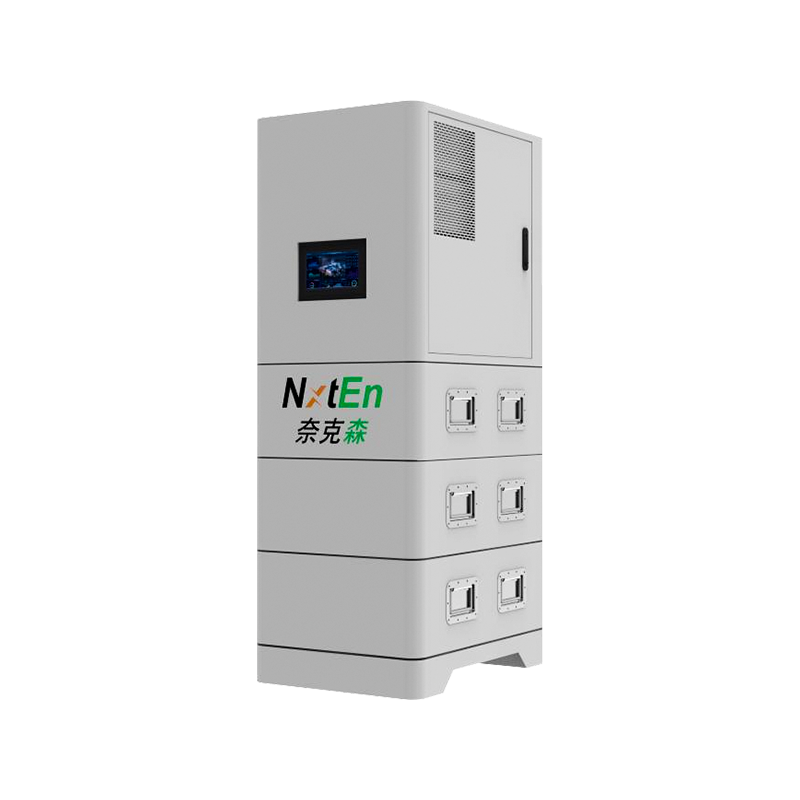
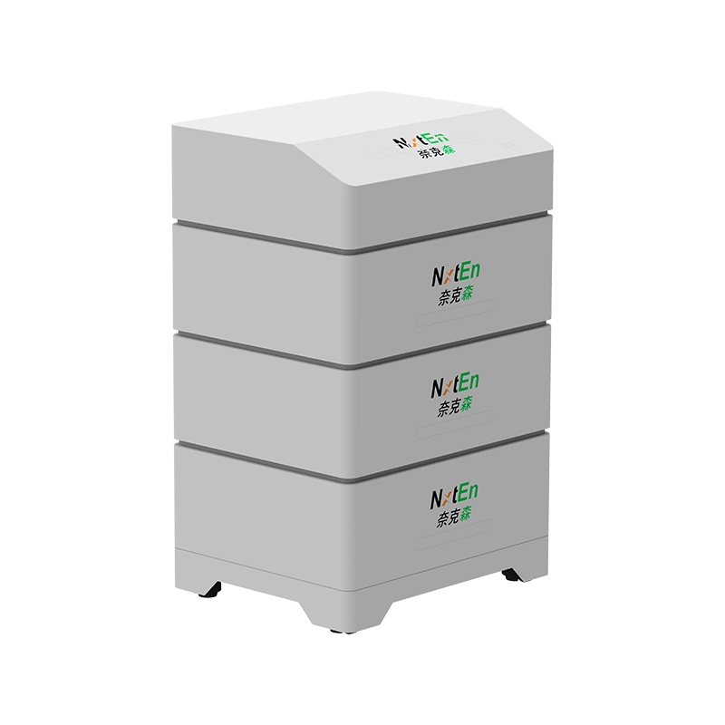
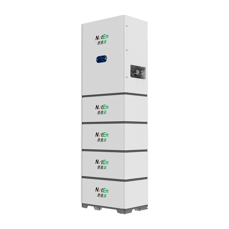 All-in-One Residential Energy Storage System with Expandable CapacityThis cabinet combines a hybrid inverter with stackable battery modules, expanding from 5 to 20 kWh to match household needs. It prioritizes solar power, enables off-peak charging, and offers quiet, compact operation with app-based monitoring.View Product →
Commercial systems are usually installed outdoors or in mechanical rooms, where modularity and service access matter. These systems run at higher C-rates and often support demand response or time-of-use arbitrage. The design must include a robust EMS with remote monitoring and a liquid-cooled thermal loop to maintain cycle life. Nxten's outdoor liquid-cooled cabinets are built for this duty, with capacities from 215 to 400 kWh.
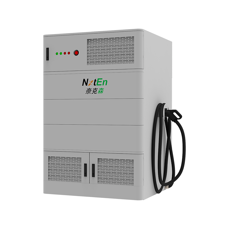
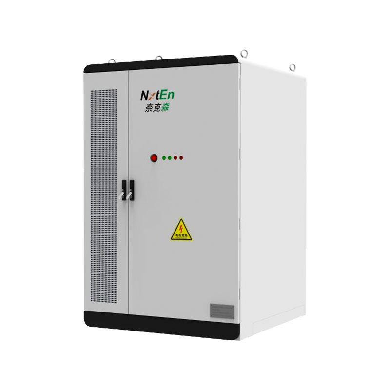
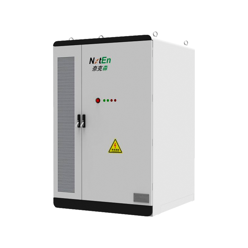 Outdoor Liquid-Cooled Commercial & Industrial Energy Storage CabinetThis cabinet integrates an LFP battery, PCS, and EMS in a modular enclosure with capacities from 215 to 233 kWh. Intelligent liquid cooling holds temperature differences within ±3°C, supporting high C-rate operation for commercial demand response and arbitrage.View Product →
Off-grid systems combine solar, wind, diesel, and storage in a single microgrid. The storage design must tolerate a higher number of deep cycles and survive frequent partial charging from renewable generation. The EMS becomes the central operator, curbing diesel generator run time and protecting battery state of charge. Here, the design effort moves from cell selection to control logic and generator coordination.
A battery energy storage system design should be treated as an iterative engineering process, not a one-time bill of materials. That means measuring actual temperatures under load, checking cell balance over months, and reviewing protection thresholds whenever the operating profile changes. By working with a manufacturer that controls the entire chain from cell to system, you avoid the gaps that appear between separate component vendors.
Design can be improved only when you have transparent data. Ask your supplier for test reports, certification documents, and the thermal simulation results behind the cooling design. The more questions you ask during the design phase, the fewer field failures you will manage later.

 +86-0574-62165160
 +86-18958222822
 No. 95-1, South Guangming Road, Simen Town, Yuyao City, Zhejiang Province, China

